
How to wire a SPDT mechanical switch
Determining the wiring configuration (Normally Open or Normally Close) to a SPDT mechanical switch can seem confusing at times. However, the concept behind it is relatively straightforward.
Wiring arrangement depends on 2 things:
- Whether the application is on the rise (i.e., trip above setpoint) or on the fall (i.e., trip below setpoint)
- Whether the load is to be turned on or off upon reaching setpoint, The load is any final element like an alarm, heater or compressor.
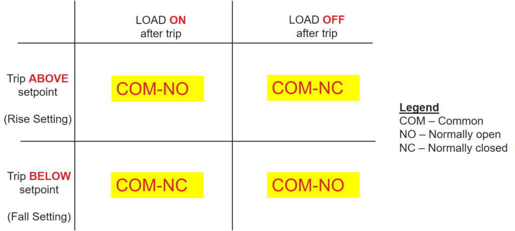
Below is a reference matrix to help you determine the SPDT wiring configuration based on your application. Applications can be fitted into one of these 4 scenarios (On-above, Off-above, On-below, Off-below). We will use 2 scenarios to explain how we derived these conclusions. A video link is embedded in this blog post for a full explanation on the 4 scenarios.
How a microswitch works
Before we dive into the 2 scenarios, we need to have a fundamental understanding of how a microswitch works. The image below shows the internal workings of a SPDT microswitch. There are 3 termination points, the NO terminal, the NC terminal and the Common(COM) terminal. There is a lever that connects the COM terminal to either the NO or NC terminal.
The mechanism of a SPDT microswitch can be summarized with a few functioning principles below:
- By default, the microswitch lever is in the COM-NC position
- Above rise setpoint (actuated), the microswitch lever is in the COM-NO position
- Below fall setpoint (deactuated), the microswitch lever is in the COM-NC position

Case 1 – Turning a load on above a setpoint (application on rise, e.g. high pressure alarm)
- At normal operation condition, process is below a setpoint. The microswitch lever is at the COM-NC position.
- Once the process is above setpoint, the lever flips to COM-NO
- Only because you want the load to be turned on above setpoint, the circuit between the COM and NO terminals has to be connected.
- Hence you wire the SPDT in a COM-NO arrangement

Case 2 – Turning a load on below a setpoint (low pressure alarm, e.g. application on fall)
- At normal operation condition, process is above a setpoint. The microswitch lever is at the COM-NO position.
- Once the process is below setpoint, the lever flips to COM-NC
- Only because you want the load to be turned on below setpoint, the circuit between the COM and NC terminals has to be connected
- Hence you wire the SPDT in a COM-NC arrangement

For a full explanation of the 4 scenarios, please review this video.
Conclusion
The wiring configurations above applies for all SPDT mechanical and electronic switches.
While most electronic switches operate on 3 wires, UE’s Excela is the industry’s first 2 wire SPDT electronic switch. The 2 wires from your SPDT switch terminals can be mapped over to the Excela switch terminals exactly. Wiring polarity does not matter. Excela combines the benefit of a switch (e.g., simplicity) and a transmitter (e.g., accuracy), making it an ideal upgrade replacement for your plant’s legacy switch infrastructure.
Visit our FAQ page to learn more about the Excela.
Please contact us for further information or discussion.
Email: marketing@ueonline.com
